
Software
PasswordTool 1.1.4
17/05/24 Filed in: Software
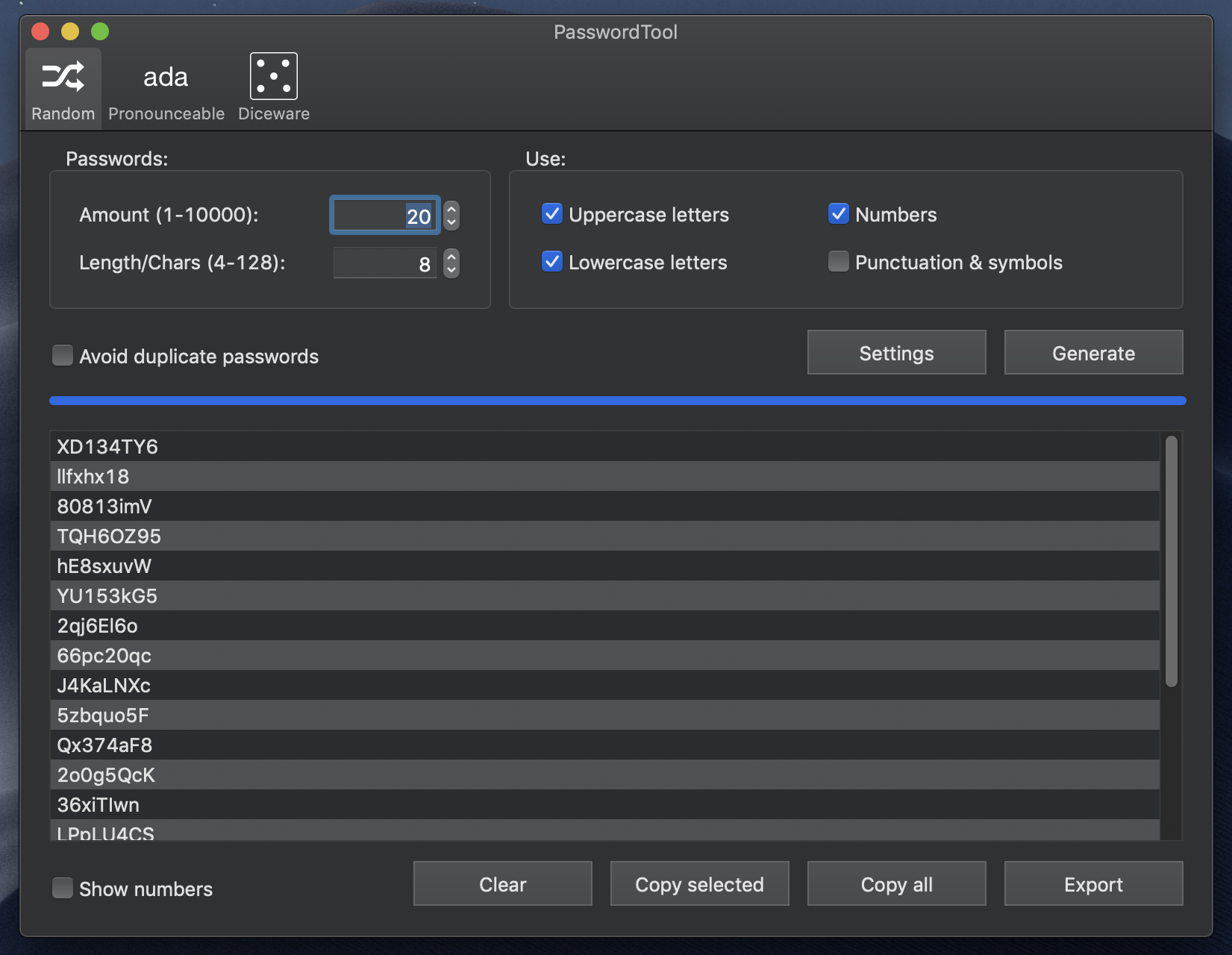
PasswordTool is a simple application that quickly and easily generates random passwords. Also you can doubleclick a password to show the MD5, SHA1, SHA256 and SHA512 hashes.
New: Improves compatibility with the current operating system version.

New: Improves compatibility with the current operating system version.
Practicum 1.6.0 released
25/04/24 Filed in: Software
New
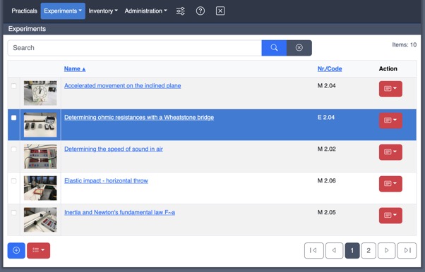
- Tidier user interface (navigation menu, system settings, action buttons, list navigation, file upload)
- Possibility to reset the password via email (if an SMTP server has been configured)
- Better performance of the program with many parallel accesses
- Improved information when filtering inventory items by status
- English localization of the program
Tutorial: Controlling RGB LED with Arduino and Xojo
Today we control an RGB-LED with Arduino and Xojo:
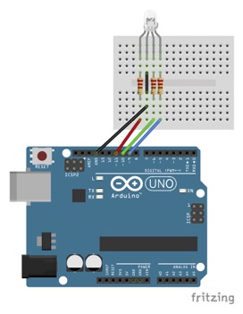
- First, you need to build the circuitry as shown in the picture below.
- Donwload the required Arduino and Xojo project files here (https://no516.com/dl/Control_RGB_Led.zip).
- Unzip the donwloaded project files.
- Connect the Arduino to your computer using an USB cable.
- Open the Arduino project file in the Arduino IDE and upload the project to the Arduino board.
- Open the Xojo project file and run the project in the Xojo IDE.
- When the application starts, you have to connect to correct the serial port (select the port from the popup menu and press the „Connect“ button)
- Now you can control the different colors of the RGB-LED with the three silders.
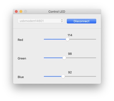
To control the RGB-LED we simply call the folowing code whenever one of the three sliders gets moved:
SerialController.Write("<"+ Str(Slider_Red.Value) + "," + Str(Slider_Green.Value) + "," + Str(Slider_Blue.Value) + ">")
Note that we use the “<“ and “>” symbols as start an end markers for the command that we send to the Arduino board. This is how the Arduino will know where a command begins and ends. The values of the sliders are separated by commas. On the Arduino board we use special code to parse the received message.
- First, you need to build the circuitry as shown in the picture below.
- Donwload the required Arduino and Xojo project files here (https://no516.com/dl/Control_RGB_Led.zip).
- Unzip the donwloaded project files.
- Connect the Arduino to your computer using an USB cable.
- Open the Arduino project file in the Arduino IDE and upload the project to the Arduino board.
- Open the Xojo project file and run the project in the Xojo IDE.
- When the application starts, you have to connect to correct the serial port (select the port from the popup menu and press the „Connect“ button)
- Now you can control the different colors of the RGB-LED with the three silders.
To control the RGB-LED we simply call the folowing code whenever one of the three sliders gets moved:
SerialController.Write("<"+ Str(Slider_Red.Value) + "," + Str(Slider_Green.Value) + "," + Str(Slider_Blue.Value) + ">")
Note that we use the “<“ and “>” symbols as start an end markers for the command that we send to the Arduino board. This is how the Arduino will know where a command begins and ends. The values of the sliders are separated by commas. On the Arduino board we use special code to parse the received message.
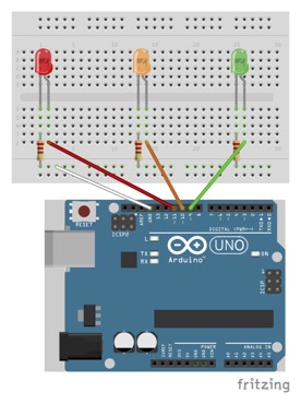
Tutorial: Controlling LED with Arduino and Xojo
It is quite easy to contral 3 LEDs with Arduino and Xojo:
- First, you need to build the circuitry as shown in the picture below.
- Donwload the required Arduino and Xojo project files here (https://no516.com/dl/Control_Led.zip).
- Unzip the donwloaded project files.
- Connect the Arduino to your computer using an USB cable.
- Open the Arduino project file in the Arduino IDE and upload the project to the Arduino board.
- Open the Xojo project file and run the project in the Xojo IDE.
- When the application starts, you have to connect to correct the serial port (select the port from the popup menu and press the „Connect“ button)
- Now you can enable the red, yellow and green LED (or turn them all off) by pressing the corresponding button.
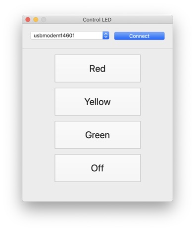
To enable the red LED we simply need to put this code in the „Action“-event of the button with caption „RED“:
SerialController.Write("r")
This command will send a single character through the serial port to the Arduino board.
To enable the yellow or green LED we use:
SerialController.Write(“y”)
or
SerialController.Write(“g”)
To turn all three LEDs off, we send the chracter „o“:
SerialController.Write(“o”)
- First, you need to build the circuitry as shown in the picture below.
- Donwload the required Arduino and Xojo project files here (https://no516.com/dl/Control_Led.zip).
- Unzip the donwloaded project files.
- Connect the Arduino to your computer using an USB cable.
- Open the Arduino project file in the Arduino IDE and upload the project to the Arduino board.
- Open the Xojo project file and run the project in the Xojo IDE.
- When the application starts, you have to connect to correct the serial port (select the port from the popup menu and press the „Connect“ button)
- Now you can enable the red, yellow and green LED (or turn them all off) by pressing the corresponding button.
To enable the red LED we simply need to put this code in the „Action“-event of the button with caption „RED“:
SerialController.Write("r")
This command will send a single character through the serial port to the Arduino board.
To enable the yellow or green LED we use:
SerialController.Write(“y”)
or
SerialController.Write(“g”)
To turn all three LEDs off, we send the chracter „o“:
SerialController.Write(“o”)
Just Code Challenge winner!
This year I took part in the „Just Code Challenge“ organized by Xojo (https://www.xojo.com) and won :-)
More information about the challenge here:
https://blog.xojo.com/2018/06/18/jump-right-in-just-code-challenge/
and the winners here:
https://forum.xojo.com/50192-just-code-challenge-winners
Thanks to the Xojo-team for the great opportunity and the great prices!
More information about the challenge here:
https://blog.xojo.com/2018/06/18/jump-right-in-just-code-challenge/
and the winners here:
https://forum.xojo.com/50192-just-code-challenge-winners
Thanks to the Xojo-team for the great opportunity and the great prices!